Technology
In This Section
Elevated Spans at 150 ft. Apart
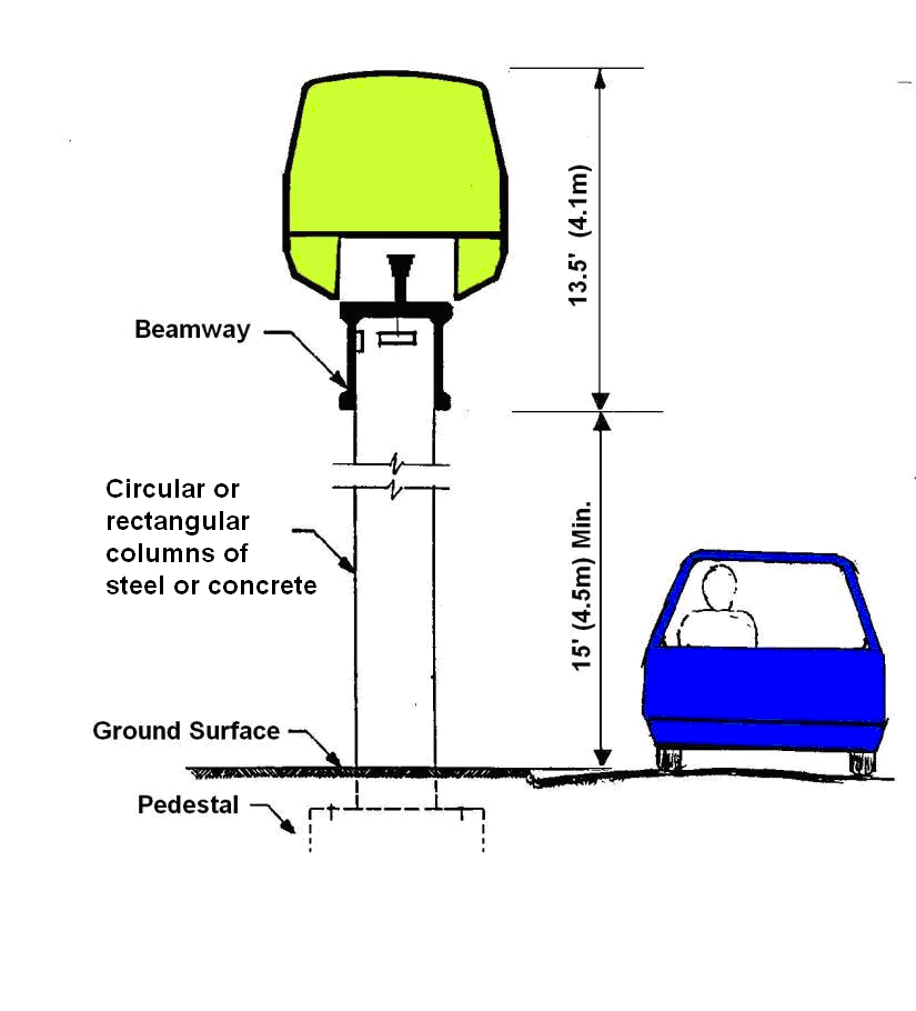
Cross Section of Single Guideway
Prefabricated
Portable Dual Guideway
Prefabricated Dual Guideway (Boot)
Guideway Components With Curved Supports
Standard Elevated Concrete Beam
Installed in
the Parking Lane along a Street
Single or
Dual Guideway
Foundation
Supports 150ft (45m) Apart

|
v A very narrow beam |
v 150 feet long spans |
|
v Minimal visual impact |
v Portable |
|
v Very small footprint |
v Easy branching |
|
v Modular (built off-site) |
|
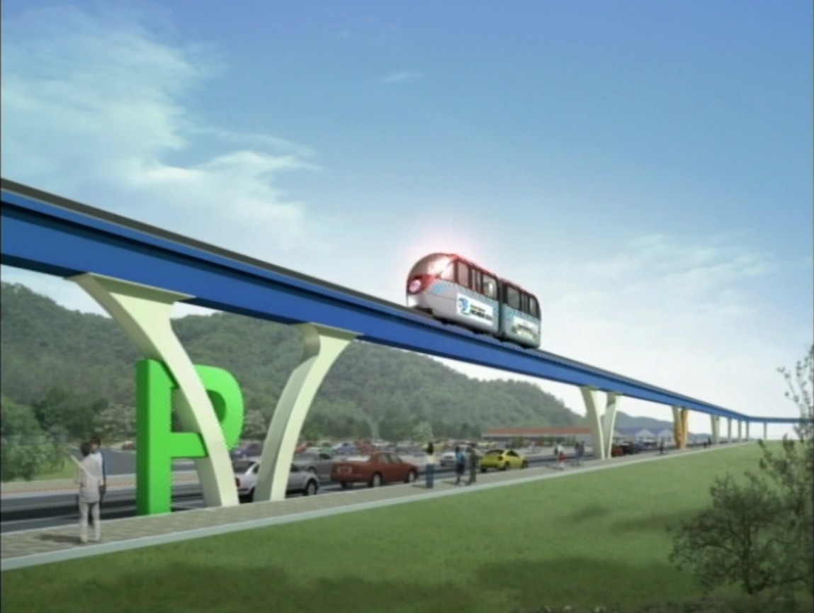
Several types of attractive elevated, lightweight, pre-manufactured guideways have been engineered by Urbanaut® which can be located off-street, having no interference with existing auto traffic. There are several optional types of structural concepts. One type consists of two elements; a curved Y-shaped column-to-beam and a center drop-in beam. These two elements allow for free spans of 150 feet between foundations which can bridge a large, busy street intersection. This system allows for flexibility in a network (route) design in that it can be easily expanded, removed or relocated if need be.
The elevated curved Y-shaped column-to-beam triangular units have a unique structural advantage, which makes the elements more slender and lighter, leading to a lower construction cost. Longer beam spans will reduce the number of foundations needed and interference with underground utilities and will have less environmental impact on the community.
The cost of construction of the guideway is 60 to 65% of the total cost of constructing an elevated monorail; therefore the elevated guideway is by far the most important portion of a total Urbanaut® System. Standardization and prefabrication with mass production of components are of paramount importance to meet cost guide lines.
There are many applications for single Urbanaut® guideways to solve critical transportation problems in our communities
1. In high density areas where the environmental impact inside the city does not allow a dual guideway, several applications and alternative solutions are possible by using a Single Urbanaut® Guideway, applying, for example, standard 3-car Urbanaut® trains that have a capacity of 6400 passengers per hour.
2. For lower or medium density residential and light commercial areas, such a Single Guideway Circulator can distributes passenger and light freight within the community, and also can serve as a connector to a high capacity Regional Urbanaut® transportation layout.
On a Single Guideway, a single Urbanaut® vehicle has a capacity of 2,160 passengers per hour and a 2-car Train (2 vehicles) has a capacity of 4,360 passengers per hour, both with 90 secs. headway.
|
|
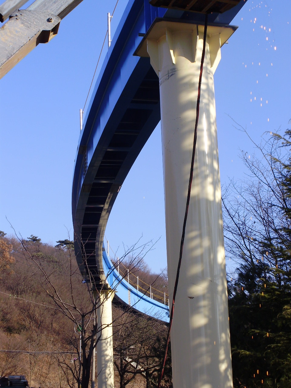
An alternative is an inexpensive guideway assembled with portable lightweight components utilizing vertical hollow columns and a beam way of composite or steel materials with a concrete running slab on top. Heating cables are installed in the runway for regions with cold climates to prevent surface icing. The guide rail on top can be made of concrete or metal.
|

This illustration show how a "Boot" support structure (invented by Mr. Svensson ) can be applied to a pile foundation. It has a unique shape and little interference with underground utilities and at the same time resists earthquake forces.
The large cantilever "Boot" structure can be located off street traffic, in the parking lane, or on a wide sidewalk as shown.

Column-To-Beam Unit
This consists of base pedestal, two curved inclined columns with a beamway on top that is cantilevered at both ends. The column-to-beam unit can be formed and precast in one piece at the site. The whole unit is then lifted in place, aligned and anchored to the foundation bolts with grouting and prestressing of the bolts. The total structure is then post-tensioned to make the guide way rigid. The slender triangular configuration of the curved column-to-beam unit has structural and economic advantages.
Drop-In-Beam Unit
The center drop-in-beam can be formed, precast, and post-tensioned on the site or in a yard. This unit is then lifted into place between two column-to-beam units and anchored with prestressing bolts to make a continuous beamway. At each end of the drop-in-beam there are bearings. One end is fixed, while the other end provides for a change in length of the beamway due to temperature differences, creep, and shrinkage. The combination of these two units allows for longer spans 150ft (45m) such as bridging across a street intersection. Such an attractive long span guideway can reduce the number of foundations and underground utility interferences up to 50%, which significantly reduces the guideway costs.
1) Column-to-Beam Unit 2. Drop-in-'Beam Unit 3) Foundation


The Y-shaped Urbanaut structure is environmentally friendly to communities

For mass production and savings in costs, Urbanant provides manufacturing information for a flexible steel form for casting of both straight and curved beams.
Prefabrication of Concrete Components
|
Rebar Skeleton of T Column The reinforcing cage is lifted as one unit into the forms, and concrete poured into a dozen of them in one day. Two days later the forms are stripped and used for another pour. |
All Columns Pre-formed on Ground in center of the street, with traffic moving in both directions |
|
The T-Column Is Lifted In Place and prestressed to anchor bolts in the foundation |
Beamways for the Urbanaut Monorail are produced to rigorous dimensional tolerances from concrete of very high strength. Curved monorail beams are fabricated in a flexible mold. Note ducts for post-tensioning at end of beam. The beams are loaded onto trailers, trucked to site and lifted directly onto top of columns |
|
90 Ft (27m) Long Beams Lifted in place. 20 of them installed in one day. |
|

Einar Svensson of the Urbanaut® Company, Inc. did the engineering innovation and was the construction engineer of the Seattle Alweg Monorail in Seattle, shown above. This portion of the original Seattle Monorail has now been removed. It was engineered for a capacity of 50,000 passengers per hour.
The curved super-elevated dual guideway is separated into 2 single guideways at the entrance to a high capacity station with center and outside passenger platforms for simultaneous loading and unloading of 2 trains.
The curved dual guideway shows three typical multiuse support structures of which any dual guideway, straight or curved sections, can be constructed:
1. A Single column for single guideways
2. A T-Column with off-set cantilevers for dual guideways
3. A large cantilever (Einar's Boot) for a dual curved guideway (super-elevated 8°)
The beamway on top consists of a prestressed and post-tensioned light weight cross-section.


